1гҖҒе®ҡд№ү
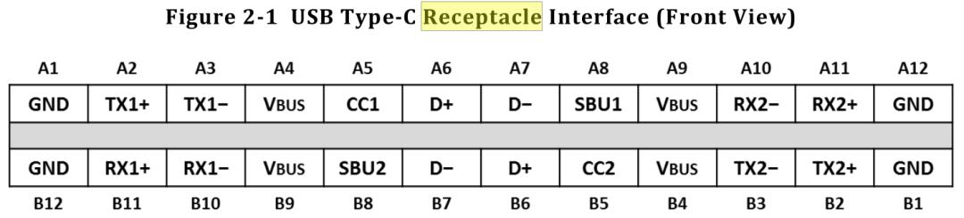
жң¬и§„иҢғе®ҡд№үдәҶ USB Type-C зҡ„ receptaclesгҖҒplugгҖҒcablesпјҢеҚіжҸ’еә§гҖҒжҸ’еӨҙгҖҒз”өзјҶгҖӮ
USB Type-C жҳҜдёҖз§Қ USB жҺҘеҸЈеӨ–еҪўж ҮеҮҶпјҢжӢҘжңүжҜ” Type-A еҸҠ Type-B еқҮе°Ҹзҡ„дҪ“з§ҜпјҢж”ҜжҢҒжӯЈеҸҚжҸ’гҖӮ
USB Type-C жңүжӣҙеӨҡзҡ„ PIN и„ҡпјҢдј з»ҹзҡ„ USB Type-A еҸӘжңүдә”дёӘ PIN и„ҡгҖӮ
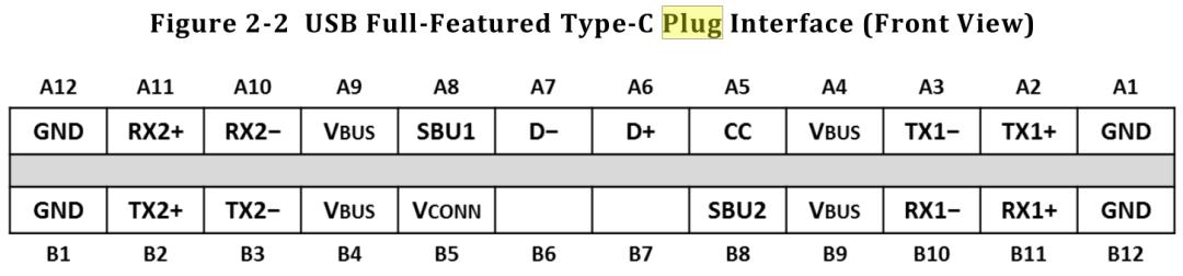
USB Type-C иҰҒжіЁж„Ҹзҡ„жҳҜпјҢжҸ’еә§е’ҢжҸ’еӨҙзҡ„ CC pinгҖҒD+/D- ж•°йҮҸдёҚдёҖж ·пјҢеҸҰеӨ–пјҢжҸ’еӨҙзҡ„ B5 жҳҜ Vconn
CCпјҡConfiguration Channel
жӢҶеҲҶеҗҺзҡ„ PIN и„ҡеҠҹиғҪеӣҫеҰӮдёӢ
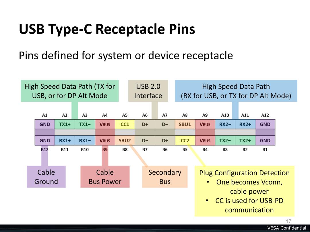
typec дё»иҰҒзҡ„ж–°еўһ PIN и„ҡ
2гҖҒCC PIN
Type-C еўһеҠ дәҶ CC1/CC2 е’Ң SBU1/SBU2пјҢCC1/CC2 еңЁ USB Type-C зҡ„еҗ„з§ҚжЁЎејҸ NormalпјҢPDпјҢALTпјҢAccessory дёӯйғҪеҸ‘жҢҘзӣёеҪ“йҮҚиҰҒзҡ„дҪңз”ЁпјӣиҖҢ SBUпјҢдё»иҰҒжҳҜдёә USB 4.0 и®ҫи®ЎпјҢ并且еңЁ ALTгҖҒAccessory жЁЎејҸд№ҹжңүе…¶дҪңз”ЁгҖӮ
CC дё»иҰҒжңүд»ҘдёӢеҠҹиғҪпјҡ
3гҖҒ Data RoleгҖҒPower Role
Type-C зҡ„ Data Role
еңЁ USB2.0 з«ҜеҸЈпјҢUSB ж №жҚ®ж•°жҚ®дј иҫ“зҡ„ж–№еҗ‘е®ҡд№үдәҶ HOST/Device/OTG дёүз§Қи§’иүІпјҢе…¶дёӯ OTG еҚіеҸҜдҪңдёә HOSTпјҢд№ҹеҸҜдҪңдёә DeviceгҖӮеңЁ Type-C дёӯпјҢд№ҹжңүзұ»дјјзҡ„е®ҡд№үпјҢеҸӘжҳҜеҗҚеӯ—жңүдәҶдәӣи®ёдҝ®ж”№гҖӮеҰӮдёӢжүҖзӨәпјҡ
пјҲ1пјүDFPпјҲDownstream Facing Portпјү
дёӢиЎҢз«ҜеҸЈпјҢеҸҜд»ҘзҗҶи§Јдёә Host жҲ–иҖ…жҳҜ HUBгҖӮDFP жҸҗдҫӣ VBUSгҖҒVCONNпјҢеҸҜд»ҘжҺҘ收数жҚ®гҖӮ
пјҲ2пјүUFPпјҲUpstream Facing Portпјү
дёҠиЎҢз«ҜеҸЈпјҢеҸҜд»ҘзҗҶи§Јдёә DeviceгҖӮUFP д»Һ VBUS дёӯеҸ–з”өпјҢ并еҸҜжҸҗдҫӣж•°жҚ®гҖӮе…ёеһӢи®ҫеӨҮжҳҜ U зӣҳпјҢ移еҠЁзЎ¬зӣҳгҖӮ
пјҲ3пјүDRDпјҲDual Role Dataпјү
еҸҢи§’иүІз«ҜеҸЈпјҢDRD ж—ўеҸҜд»ҘеҒҡ DFP д№ҹеҸҜд»ҘеҒҡ UFPпјҢд№ҹеҸҜд»ҘеңЁ DFP дёҺ UFP й—ҙеҠЁжҖҒеҲҮжҚўгҖӮ
Type-C зҡ„ Power Role
ж №жҚ® USB PORT зҡ„дҫӣз”өпјҲеҸ—з”өпјүжғ…еҶөпјҢUSB Type-C е°Ҷ port еҲ’еҲҶдёә SourceгҖҒSink гҖҒDRP(Dual-Role-Power)
| 姓еҗҚ | е№ҙйҫ„ |
|---|---|
| Sink | Port asserting Rd on CC and when attached is consuming power from VBUs |
| Source | Port asserting Rp on CC and when attached is providing power over VBus |
| DRP(Dual-Role-Power) | A USB port that can operate as either a Source or a Sink |
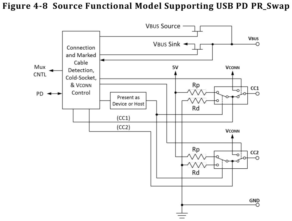
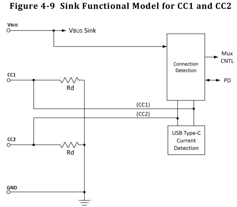
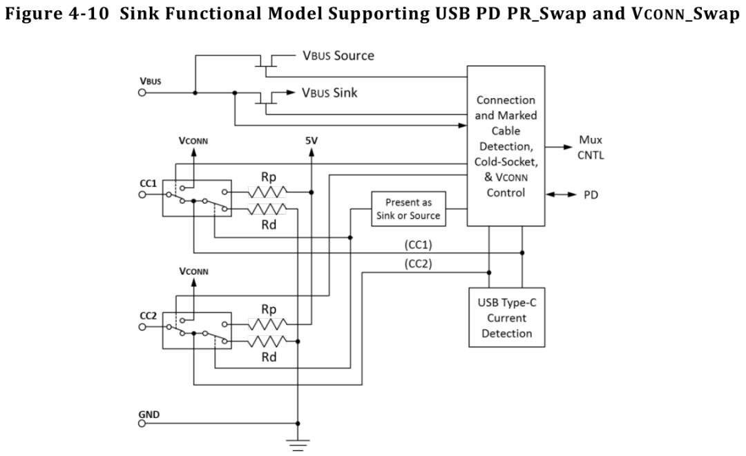
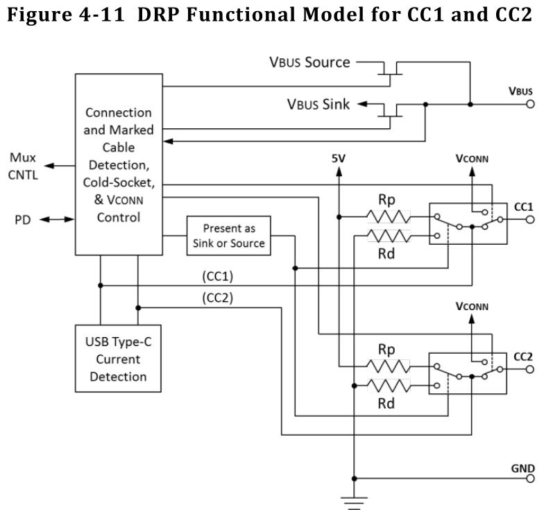
4гҖҒ硬件еҺҹзҗҶеӣҫ
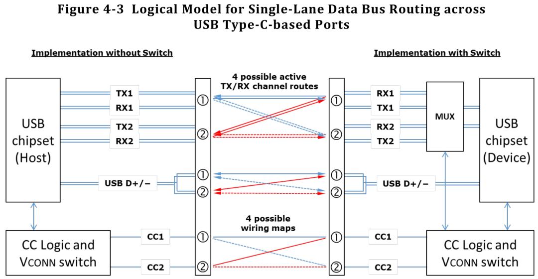
5гҖҒType-C Data Bus Routing

6гҖҒType-C Attach/Detach Detection
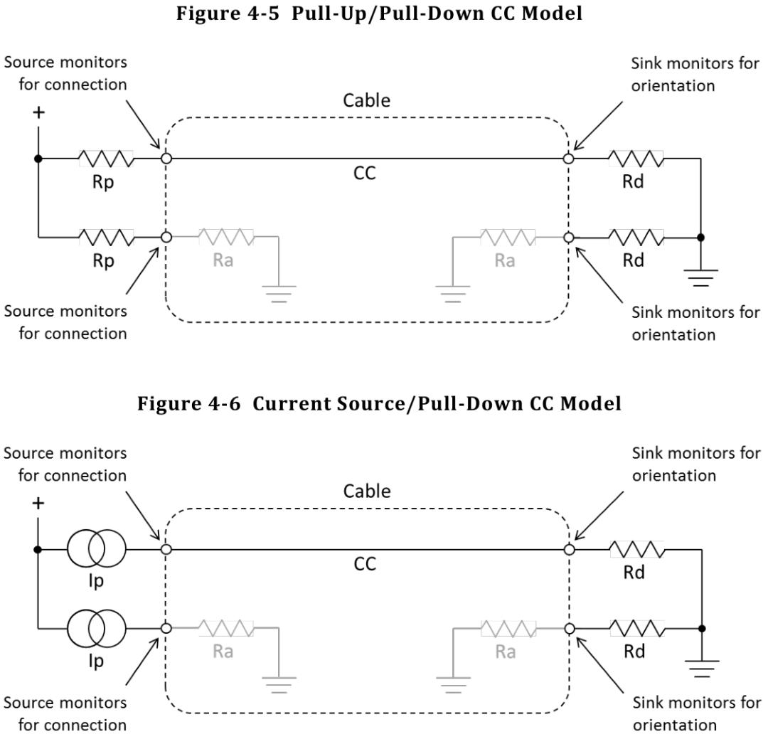
Pull-Up Resistance (Rp)
Power: Source,Provider
Data: DFPпјҢHost
Vconn Source: for eMark IC
Pull-Down Resistance (Rd)
Power: Sink, Consumer
Data: UFP,Device
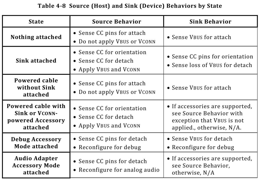
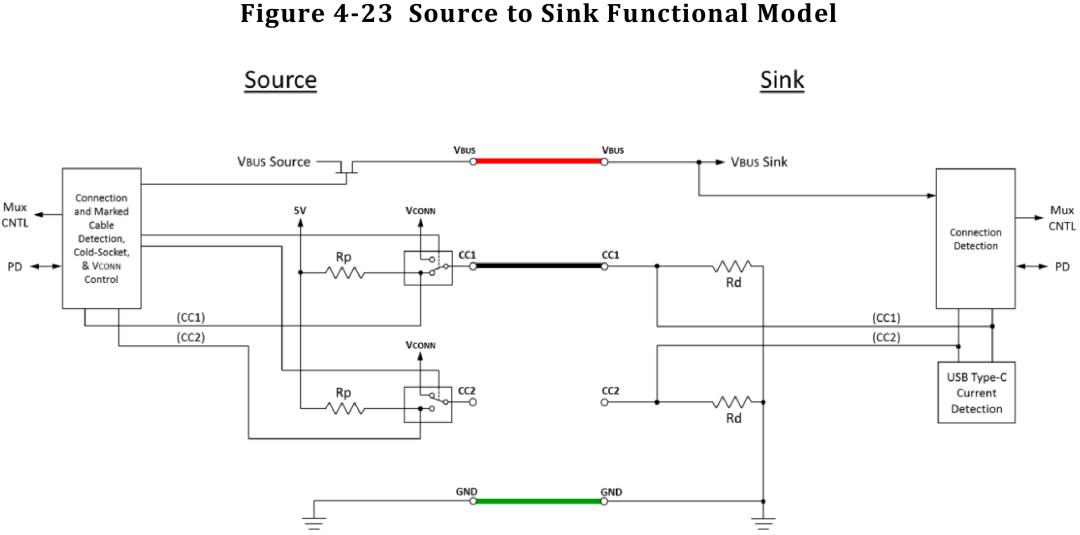
еҠҹиғҪеӣҫиҜҰз»ҶиҜҙжҳҺ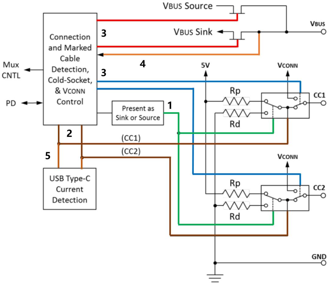
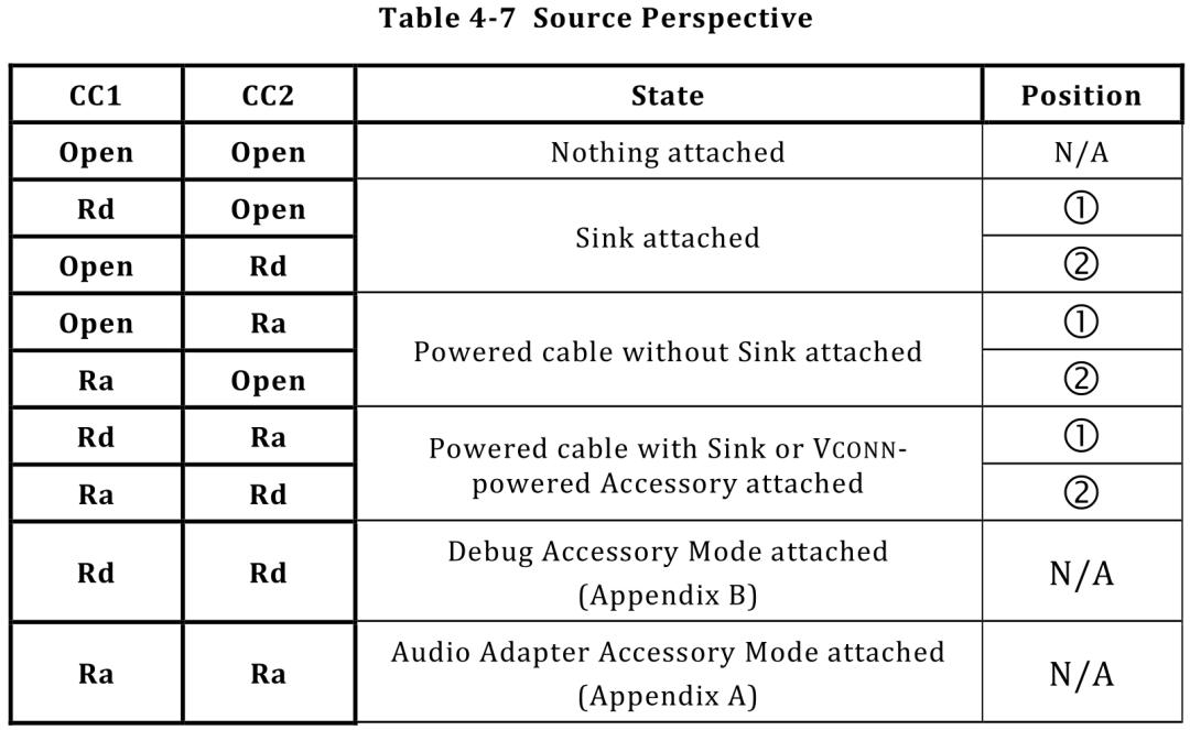
Source
initially the Source has VBUS disabled.
Sink
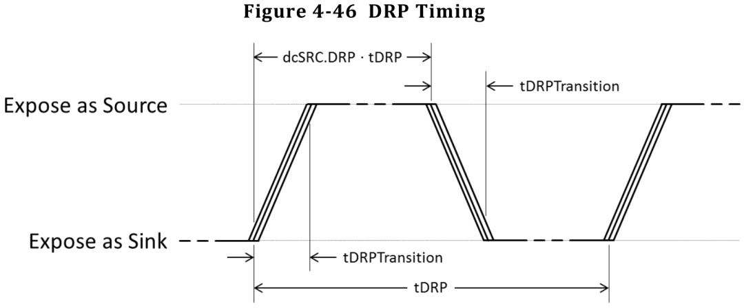
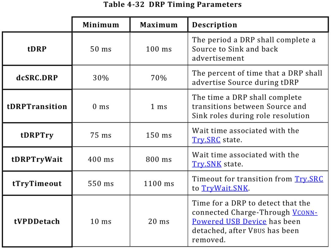
7гҖҒTiming Parameters
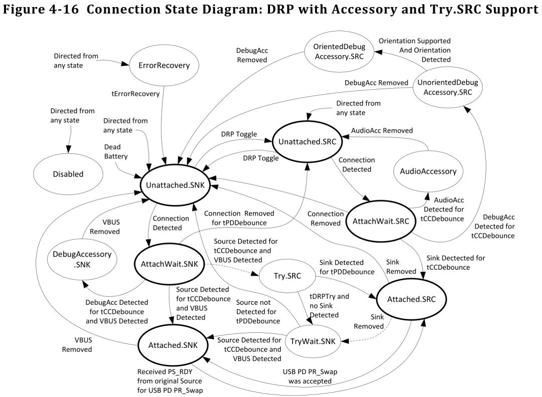
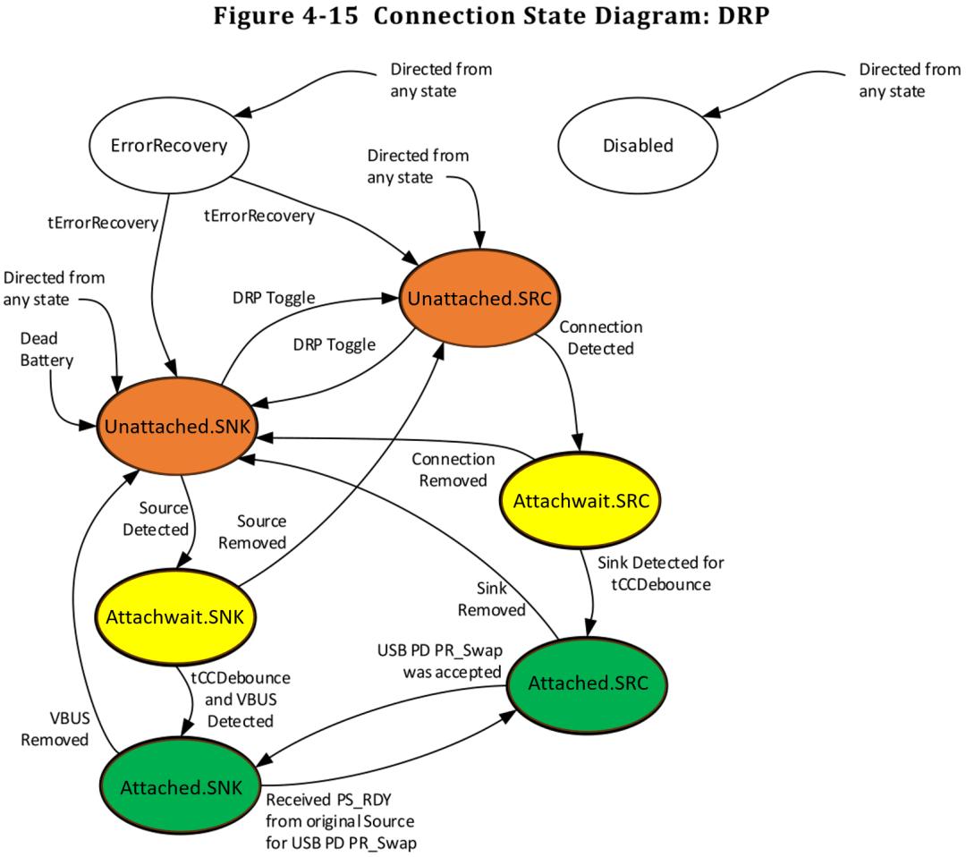
8гҖҒState Diagram
1. No TA/Device ConnectedгҖҒDetached or cable only
HW-DRP toggling
SW-idle
2.TA Connected stage1
HW-detected Rp/Rd,expose as Sink/SourceпјҢalert SW cc-change
SW-receive cc-change, waiting for tCCDebounce to make sure it's not a noise
3.TA Connected stage2
HW-detected Vbus_valid alert SW ps_change
SW-after tCCDebounce, check vbus; if valid alert system TA connected and start PD communication;